Smart Thermostat Wiring Guide: C-Wire, Compatibility, and Installation
Quick answer
Smart thermostat installation starts with compatibility, not wire color. Confirm system type, terminal labels, voltage class, C-wire or adapter plan, heat-pump reversing valve behavior, and manufacturer checker results before disconnecting anything. Stop and hire help for line-voltage, communicating, dual-transformer, zoned, humidifier, or dual-fuel systems you cannot positively identify.
Common questions
- Can wire color identify thermostat terminals?
- No. Terminal labels matter more than color because previous installers may have used different conductor colors. Photograph and label the existing terminal positions before moving wires.
- When should a smart thermostat installation stop?
- Stop if the thermostat controls line voltage, the system is communicating/proprietary, there are multiple transformers, the heat-pump O/B behavior is unknown, wires are not clearly labeled, or the HVAC equipment will not power down safely.
Source note: Reviewed July 2026 against ENERGY STAR smart thermostat guidance and manufacturer compatibility documentation from Google Nest and ecobee. HVAC equipment manuals, thermostat manuals, local code, and qualified HVAC/electrical technicians control final work.
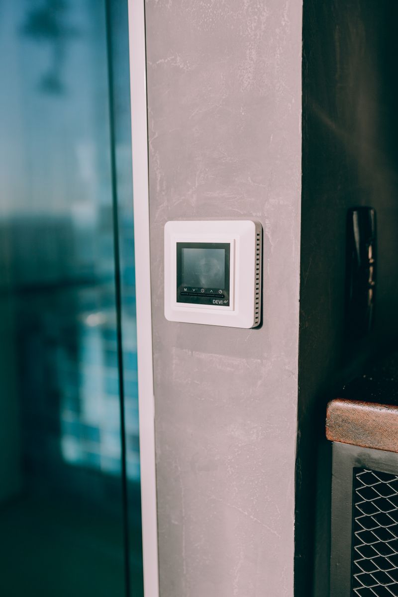
Smart thermostats can improve scheduling, comfort, and system visibility, but the wiring step is where good installs and bad guesses separate. The goal is not to memorize wire colors. The goal is to prove the system type, voltage class, terminal labels, C-wire plan, and manufacturer compatibility before you disconnect anything.
ENERGY STAR notes that smart thermostat compatibility depends heavily on HVAC system type, and complex variable-speed, multistage, or zoned systems may need professional installation. Use the thermostat maker’s checker before buying: Google publishes Nest thermostat compatibility guidance, and ecobee provides a thermostat compatibility checker.
Compatibility Decision Matrix
| Existing condition | DIY risk level | Next action |
|---|---|---|
| 24V conventional furnace/AC with R, C, W, Y, G clearly labeled | Lower | Photograph, label, verify checker result, install per manual |
| 24V system with spare unused conductor | Moderate | Confirm same spare conductor at control board before using as C |
| No C-wire and simple conventional system | Moderate | Use manufacturer-approved adapter only after checker confirms fit |
| Heat pump with O/B and auxiliary heat | Moderate to high | Confirm brand-specific reversing-valve behavior and aux setup |
| Dual-fuel heat pump with gas backup | High | Use HVAC pro unless you can verify staging and lockout logic |
| Zoned, communicating, proprietary, or variable-speed system | High | Use manufacturer/HVAC professional path |
| Line-voltage thermostat for baseboard or wall heater | Stop | Do not install a 24V smart thermostat |
Thermostat Handoff Worksheet
Record these before removing wires:
| Field note | What to capture | Why it matters |
|---|---|---|
| Old thermostat photo | Straight-on image showing terminal labels | Recovery reference if setup fails |
| HVAC equipment model | Furnace, air handler, heat pump, boiler, zone panel | Compatibility depends on equipment, not only thermostat |
| Terminal labels in use | R/Rc/Rh, C, W/W2, Y/Y2, G, O/B, Aux/E, S/S1/S2 | Determines stages and accessory behavior |
| Unused conductors | Color and whether same wire appears at control board | Avoids assuming a spare wire is connected |
| Transformer count | One R source or separate Rc/Rh | Dual-transformer systems can break adapter assumptions |
| Voltage class | 24V low-voltage vs. 120/240V line-voltage | Prevents incompatible and dangerous installs |
| Compatibility checker result | Brand, model, screenshot/date | Keeps the setup tied to manufacturer guidance |
Before You Start: Check Compatibility
Not all HVAC systems are compatible with every smart thermostat. Before buying, verify compatibility using the thermostat manufacturer’s compatibility checker.
Key compatibility questions:
-
What type of HVAC system do you have?
- Conventional forced air (furnace + AC)
- Heat pump (cooling + electric resistance heat)
- Heat pump with auxiliary gas heat
- Boiler/radiant heat
- Multi-stage systems (2-stage heat or cool)
-
How many conductors does your existing thermostat cable have? Remove the thermostat cover and count the wires connected to terminals plus any unused wires taped aside. The number of wires determines which features you can support and whether you need a C-wire workaround.
-
Is there a C-wire connection available? (More on this below)
-
Is the system low-voltage (24V) or line-voltage (120V or 240V)? Smart thermostats are designed for 24V systems only. Line-voltage thermostats (often found with electric baseboard heat) require a different thermostat type — most smart thermostats are not compatible.
Understanding Your Existing Wiring
The first step in any thermostat replacement is documenting the existing wiring.
Step 1: Photograph Before Disconnecting
Before removing any wires, photograph the existing thermostat wiring clearly. This is your reference if anything goes wrong.
Step 2: Label Each Wire
Use tape flags or sticker labels to mark each wire with its terminal letter before removing it. The terminal labels (R, C, W, Y, G, O, B, etc.) are what matter — not the wire color.
Step 3: Note the Cable at the HVAC Unit
At the furnace or air handler, find where the thermostat cable connects to the control board only if you can turn the equipment off safely and the service panel is intended for homeowner access. This is where a technician or qualified DIYer confirms whether an unused conductor is actually available as C. If the panel exposes line-voltage parts, stop.
The Standard 5-Wire Thermostat System
The most common configuration in homes with forced air heating and cooling:
| Wire Color | Terminal | Function |
|---|---|---|
| Red | R (or Rh) | 24V power from transformer |
| White | W | Heat (call for heat) |
| Yellow | Y | Cooling (call for cool) |
| Green | G | Fan (blower) |
| Blue or Black | C | Common (return path for 24V power) |
If you have 5 wires connected and one of them is blue or black going to a C terminal, you’re in the best-case scenario — all you need for full smart thermostat compatibility.
The C-Wire Problem — and Solutions
The C-wire (Common) is the return path for the 24V power circuit. It completes the circuit that allows the smart thermostat to draw continuous power for its Wi-Fi radio, display, and processing.
Older thermostats could “steal” power from the R wire by briefly completing the circuit through a load (heater, fan) in ways that were imperceptible to the HVAC system. Smart thermostats draw too much continuous current for this method to work reliably.
If you don’t have a C-wire:
Option 1: Use an Unused Wire in the Cable
If your thermostat cable has 5 or more conductors but only 4 are connected (common in homes with either heat or cooling but not both), you likely have an unused wire you can repurpose.
How to convert an unused wire to C-wire:
- At the thermostat, connect the unused wire to the C terminal
- At the HVAC control board, connect that same wire to the C terminal on the board
- Done — you now have a functioning C-wire
This is the cleanest solution when a spare conductor exists and both ends are positively identified. It is not a color-matching exercise.
Option 2: Ecobee Add-a-Wire / Nest Power Connector
Some smart thermostats include an adapter that uses the R and C terminals in a way that effectively creates a C-wire from a 2 or 4-wire system.
Ecobee’s Power Extender Kit connects at the furnace/air handler on compatible systems and is designed for homes without a C-wire. ecobee says to use its compatibility checker before adding the kit, and its support materials note limitations such as dual-transformer and heat-only systems.
Nest’s Power Connector works similarly. Google’s Nest Power Connector guidance explains how it connects at the HVAC unit for compatible systems without a C-wire.
Both solutions work well in most systems but can cause issues with some HVAC systems, particularly those with sensitive control boards. Check compatibility first.
Option 3: Run New 18/5 Cable
The definitive solution: run a new 5-conductor (or 6-conductor for heat pumps) 18 AWG thermostat cable from the air handler to the thermostat location.
18/5 thermostat cable (approximately $0.20–$0.40/foot) is widely available. For typical thermostat runs of 20–50 feet, material cost is minimal. If the wall cavity is accessible, this is a worthwhile DIY project. If not, it may require an HVAC technician or electrician to fish the new wire.
Option 4: Plug-in C-Wire Adapter
If an outlet is accessible near the thermostat, a plug-in 24V adapter can provide the C connection. This is functional but not elegant. Companies like Venstar and Bosch sell these adapters.
Heat Pump Thermostat Wiring
Heat pumps add complexity because they use the same outdoor unit for both heating and cooling — a reversing valve changes the refrigerant flow direction. This requires additional thermostat wires:
Standard Heat Pump Wiring (4+C+O/B)
| Wire Color | Terminal | Function |
|---|---|---|
| Red | R | 24V power |
| White | W/Aux | Auxiliary heat (usually electric resistance strips) |
| Yellow | Y | Compressor |
| Green | G | Fan |
| Blue or Black | C | Common |
| Orange | O | Reversing valve (energized in cooling for Carrier, etc.) |
| Dark Blue | B | Reversing valve (energized in heating for Rheem/Ruud, Trane, American Standard) |
O vs B: The reversing valve terminal designation depends on the heat pump brand:
- O terminal: Energize for cooling (Carrier, Lennox, York, most brands)
- B terminal: Energize for heating (Rheem, Ruud, some Trane)
Most smart thermostats have an O/B terminal where you configure which mode energizes the reversing valve during setup. Verify with your heat pump’s documentation.
Heat Pump with Gas Auxiliary Heat
Dual-fuel heat pumps that use a gas furnace as backup heat require all heat pump wires plus an additional wire for the gas furnace heat stage. This typically requires a 7+ conductor thermostat cable.
Step-by-Step Smart Thermostat Installation
Tools Needed
- Phillips head screwdriver
- Small flathead screwdriver (for terminal screws)
- Non-contact voltage tester
- Drill with anchors (for mounting)
- Smartphone or tablet (for app-guided setup)
Step 1: Turn Off the HVAC
Turn off the furnace/air handler at the unit’s service switch (a standard toggle switch usually located on the unit or nearby). Also turn off the thermostat’s circuit breaker if you can identify it.
Verify with a non-contact voltage tester at the thermostat that no live voltage is present.
Step 2: Remove the Old Thermostat
Remove the thermostat cover and take the photograph mentioned earlier. Label each wire with its terminal. Loosen each terminal screw and remove the wires. Remove the thermostat base from the wall.
If wires fall into the wall: Use tape or a pencil to prevent them from slipping into the wall cavity before you can connect them to the new base.
Step 3: Install the New Base
Level the new thermostat base on the wall and mark the mounting hole locations. Drill and insert anchors if needed (drywall anchors for non-stud mounting). Secure the base with screws.
Thread the thermostat wires through the cable opening in the new base.
Step 4: Connect the Wires
Follow the new thermostat’s wiring diagram, connecting each labeled wire to the correct terminal on the new base. Refer to your terminal-to-wire mapping from Step 2.
Most smart thermostats have clearly labeled terminals with color-coded guidance in the app or instructions. If there’s any uncertainty about which wire connects where, consult the thermostat manufacturer’s compatibility checker with your system’s specifics.
Gently tug each wire after connecting to verify it’s seated.
Step 5: Attach the Display and Configure
Attach the thermostat display to the base. Restore power (turn the circuit breaker and unit service switch back on).
Follow the thermostat’s app-guided setup:
- Connect to your Wi-Fi network
- Configure system type (conventional, heat pump, multi-stage, etc.)
- Set heating and cooling stages based on your wiring
- For heat pumps: configure O/B terminal behavior
- Test heating, cooling, and fan operation before declaring success
Step 6: Test All Functions
With the system running, verify:
- Heat call causes the furnace/heat pump to run
- Cool call causes the AC/compressor to run
- Fan call runs the blower only
- Temperature readings are accurate (within 2°F of a known-good thermometer in the same room)
- For smart thermostats: app connectivity and remote control work
Recommended Smart Thermostats
Ecobee Smart Premium Thermostat (~$250)
The most broadly compatible smart thermostat on the market. Handles conventional, heat pump, dual-fuel, multi-stage, and zoned systems. Includes a room sensor for multi-room temperature awareness. Works with Apple HomeKit, Alexa, Google Home, and SmartThings. Includes Add-a-Wire adapter for C-wire workaround.
Best for: Complex HVAC systems, multi-room awareness, Apple HomeKit users
Google Nest Learning Thermostat (4th Gen) (~$180)
Google’s flagship thermostat learns your schedule over the first week and programs itself. Excellent app interface and Google Assistant integration. Compatible with most conventional and heat pump systems. Requires C-wire or Nest Power Connector.
Best for: Conventional forced air, those in the Google ecosystem
Honeywell Home T9 (~$170)
Strong HVAC compatibility, built-in humidity sensing, and Honeywell’s proven track record in HVAC controls. Multiple room sensors available. Works with Alexa and Google Home.
Best for: Homeowners who prefer a well-established HVAC brand
Budget Smart Thermostat (~$60)
The most affordable smart thermostat from a name brand. Alexa built-in, basic scheduling, and adequate compatibility for simple forced-air systems. For those who want smart thermostat basics without the premium price.
Best for: Budget-conscious users with simple HVAC systems, Alexa households
Smart thermostat installation can be a reasonable homeowner project on a simple, clearly labeled 24V system. It is not a good guessing project. Take the time to document the existing wiring, use the manufacturer compatibility checker, address the C-wire plan before starting, and call an HVAC technician or electrician when the system type is not obvious.
Document HVAC wiring before changing controls
These resources connect thermostat compatibility with safe electrical handoff notes, low-voltage wiring context, and circuit symptoms.
- Electrician handoff checklist
Record visible labels, photos, system notes, and stop conditions before a service visit.
- Generator transfer handoff worksheet
Keep thermostat, HVAC, and essential-load notes aligned for backup-power planning.
- Low-voltage wiring guide
Understand why low-voltage controls are different from line-voltage circuits.
- Lighting circuit troubleshooting
Use symptom documentation habits without opening energized equipment.
- Circuit breaker types
Review why repeatedly resetting protective devices is not troubleshooting.
- Whole-house generator sizing
Keep thermostat, HVAC, and backup-power load notes aligned before discussing transfer equipment.

Amperage HQ Editorial Team
Independent trade-focused editorial team