Outlet Tester Light Meanings and Limitations
Quick answer
Match the illuminated lamps to the legend printed on your exact outlet tester; patterns are not universal. Treat every fault indication as a reason to stop and investigate, and remember that a 'correct' result only rules out a limited set of simple wiring errors.
Common questions
- Does two amber lights mean an outlet is wired correctly?
- That is a common pattern on some three-light testers, including familiar North American models, but you must use the legend on the exact tester. A correct indication still cannot verify ground quality or rule out every wiring defect.
- Can an outlet tester prove the power is off?
- No. An all-dark tester can mean an open hot, a dead circuit, poor blade contact, damage, or operation outside the tester's design. Absence-of-voltage verification for electrical work requires an appropriate method and qualified judgment.
Source note: Limitations checked in August 2026 against Klein Tools receptacle-tester instructions. Indicator order, GFCI procedure, voltage range, and detectable faults vary by model.
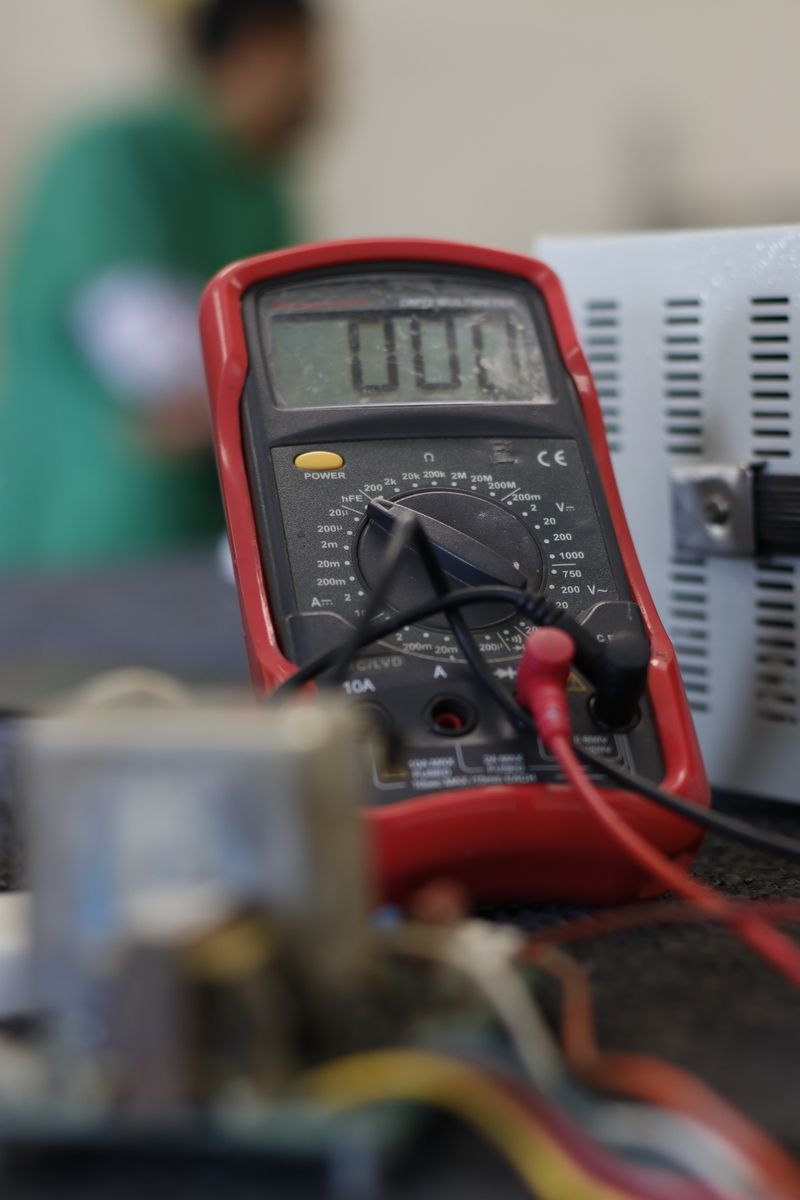
Read the light pattern from the legend on your exact tester—not from memory or a chart online. Three-light receptacle testers often use similar red and amber lamps, but lamp order, labels, electronics, voltage range, and GFCI functions vary. A “correct” pattern means only that the tester recognized one expected relationship among hot, neutral, and ground.
It does not certify the outlet, measure ground quality, prove safe de-energization, find every loose connection, or inspect the rest of the circuit. The manufacturer’s limitations are as important as the light legend.
Practical interpretation of common labels
First match the illuminated lamps to the chart printed on the tester body. Then interpret the named result:
| Tester label | What it usually means | Safe next step |
|---|---|---|
| Correct | The simple hot-neutral-ground relationship matches the tester’s expected pattern | Record the result, but continue required visual and functional checks |
| Open ground | The tester sees a hot-neutral supply but not its expected equipment-grounding path | Stop using the result as proof of grounding; arrange qualified evaluation |
| Open neutral | The expected neutral return path is missing | Unplug loads, stop using the receptacle, and call an electrician |
| Open hot | The tester does not detect the expected energized hot path | Treat as undetermined, not proven safe; check upstream protection without opening equipment |
| Hot/neutral reversed or reverse polarity | Hot and neutral appear transposed | Stop using the receptacle until corrected |
| Hot/ground reversed | The measured relationship resembles a severe miswire | Do not touch grounded equipment; arrange prompt professional diagnosis |
Some testers describe the last condition differently, and multiple real faults can create misleading patterns. Do not move wires to make the lights match. Use the standard outlet wiring guide only to understand terminology; repairing a fault indication requires de-energization, conductor identification, and appropriate skill.
A safe test sequence
- Inspect the tester. Do not use it if the case, blades, button, or lamps are damaged.
- Read its rating and instructions. Confirm it is designed for the receptacle, nominal voltage, location, and task.
- Prove it on a known-live, correctly wired receptacle. This confirms basic operation before the target test.
- Remove connected loads when the manufacturer directs. Other devices on the circuit can interfere with readings.
- Insert it fully without touching metal. Stop for looseness, heat, odor, buzzing, discoloration, sparks, or damage.
- Compare the lamps with the tester’s own legend. Photograph the result and tester model.
- Repeat the known-live check afterward when the result will inform safety decisions.
Never insert a tester into a receptacle that has sparked, is wet, is cracked, or will not grip a plug. Use the outlet-sparking safety guide instead and leave the circuit off when safe.
What a three-light tester cannot detect
Klein’s current kit instructions identify several conditions outside a basic tester’s capability:
- Quality of the ground path
- Multiple hot conductors where the tester expects one
- Combinations of defects that can mask or mimic another pattern
- Reversal of grounded and grounding conductors—neutral and equipment ground
A basic tester also does not establish:
- Terminal torque or receptacle contact tension
- A loose, heat-damaged, or intermittent upstream connection
- Conductor size, material, insulation condition, or breaker compatibility
- Voltage drop under meaningful load
- Whether neutral and ground are improperly bonded elsewhere
- AFCI performance
- Correct box fill, splices, weather rating, or tamper resistance
- Compliance of every downstream receptacle
This is why “two amber lights” cannot close an electrical inspection. The home buyer electrical checklist treats a plug-in result as one screening observation among many, not a certificate.
Why an all-dark result is not proof of de-energization
No lights can match the tester’s open hot legend, but it can also result from a tripped upstream GFCI, switched receptacle, failed device, poor contact, supply outage, damaged tester, or circuit outside its operating range. Follow the dead-outlet diagnostic flow for safe visible checks, but do not treat an all-dark tester as proof that the wiring is de-energized. A receptacle tester is not the complete live-dead-live verification method used before electrical work.
The voltage tester comparison explains why non-contact, contact, solenoid, and meter-based tools answer different questions. Panel and exposed-conductor testing should be performed by a qualified person using appropriately rated equipment and protective practices.
Using the GFCI test button
A receptacle tester with a GFCI button creates a small test current intended to trip compatible ground-fault protection. Follow the tester and GFCI manufacturers’ instructions exactly.
Before using the button:
- Confirm the ordinary light pattern is acceptable for that model.
- Identify what will lose power and protect sensitive or critical loads.
- Do not test where interruption would create a hazard.
- Press only for the specified time.
- Confirm power at the receptacle turns off, then reset at the correct GFCI device or breaker.
- Stop if it will not trip, will not reset, trips upstream unexpectedly, or shows a wiring fault.
The external tester’s button may rely on an equipment-grounding path and may not operate as expected on an ungrounded receptacle, even where a GFCI-protected replacement is allowed and labeled. The built-in TEST button on the GFCI device tests its own mechanism and should be used according to that manufacturer’s instructions. Read the GFCI reset troubleshooting guide before attempting another reset.
Turn a result into a useful handoff
Record:
- Tester manufacturer and model
- Exact illuminated-lamp pattern and printed result
- Receptacle location and breaker label
- Whether the outlet is switched or GFCI-protected upstream
- GFCI button behavior and reset location
- Connected loads removed before testing
- Heat, looseness, odor, sound, discoloration, or intermittent power
- Results at nearby receptacles without opening any boxes
Do not keep testing after a dangerous sign or use a three-to-two-prong adapter to change the indication. Mark the receptacle out of service and use the electrician handoff checklist.
The Klein RT210 product page describes the tool as detecting the most common wiring problems, not every defect. Klein’s newer receptacle-tester kit instructions explicitly list undetected conditions and warn that connected equipment can cause erroneous readings. The correct conclusion from a plug-in tester is a screening result with limits, followed by the appropriate qualified inspection.

Amperage HQ Editorial Team
Independent trade-focused editorial team